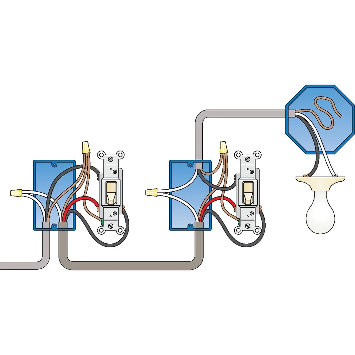
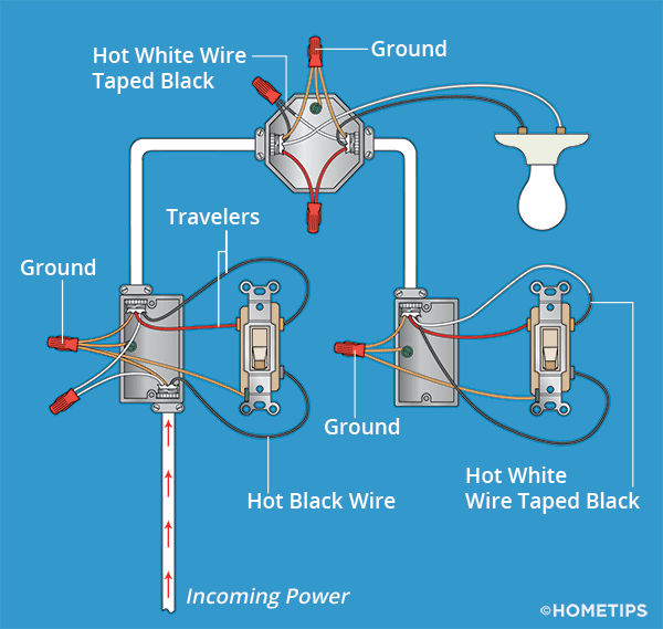
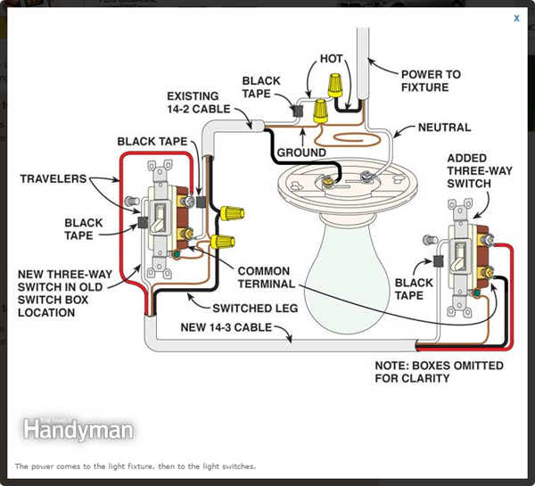
Understanding the 3 Way Wiring Switch Diagram is crucial for anyone working with electrical systems. This diagram shows the connections between three switches that control a single light or set of lights. By following the diagram, you can wire the switches correctly to control the lights from multiple locations.
Importance of 3 Way Wiring Switch Diagram
- Allows for control of lights from multiple locations
- Ensures proper wiring connections
- Prevents electrical issues and safety hazards
Reading and Interpreting 3 Way Wiring Switch Diagram
When looking at a 3 Way Wiring Switch Diagram, it’s important to understand the symbols and connections. The diagram typically shows the switches, light fixture, and wiring connections between them. Each switch is labeled as either a “common” terminal or “traveler” terminal. The common terminal is connected to the power source, while the traveler terminals allow for communication between the switches.
Using 3 Way Wiring Switch Diagram for Troubleshooting
When facing electrical problems with a 3-way switch setup, referring to the wiring diagram can help identify the issue. Common problems include incorrect wiring connections, faulty switches, or damaged wires. By comparing the actual wiring with the diagram, you can pinpoint the problem area and make the necessary corrections.
Safety Tips for Working with 3 Way Wiring Switch Diagram
- Always turn off the power before working on electrical systems
- Use insulated tools to avoid electric shock
- Double-check connections to ensure they are secure
- Consult a professional if unsure about any wiring procedures
3 Way Wiring Switch Diagram
3-Way Switch Wiring Explained – MEP Academy

How to Wire a 3-Way Switch: Wiring Diagram | Dengarden

Standard 3 Way Switch Wiring Diagram – Diysus

How To Wire Three-Way Light Switches | HomeTips

Basic 3 Way Switch Wiring – 3 Way Switch Wiring Diagram & Schematic

How To Wire A 3-Way Switch – Gotta Go Do It Yourself
