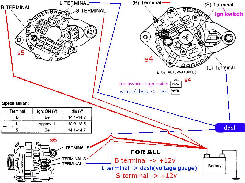
When it comes to understanding the complex electrical system of a vehicle, having a clear understanding of the alternator wiring schematic is crucial. The alternator wiring schematic is a detailed diagram that illustrates the connections and functions of the various components within the vehicle’s charging system. By studying this schematic, mechanics can diagnose and repair electrical issues efficiently.
Why Alternator Wiring Schematic are Essential
- Provides a visual representation of the electrical connections in the charging system
- Aids in understanding how the alternator generates power and distributes it to the battery
- Helps in identifying faulty wiring or components that may be causing charging problems
- Essential for proper installation of a new alternator or other charging system components
How to Read and Interpret Alternator Wiring Schematic
Reading and interpreting an alternator wiring schematic may seem daunting at first, but with a systematic approach, it can be easily understood. Here are some tips:
- Start by familiarizing yourself with the symbols and abbreviations used in the schematic
- Follow the flow of electricity from the alternator to the battery and other components
- Identify key components such as the voltage regulator, diodes, and connections to the battery
- Pay attention to the color-coding of the wires to ensure correct connections
Using Alternator Wiring Schematic for Troubleshooting Electrical Problems
When faced with electrical issues in a vehicle, the alternator wiring schematic can be a valuable tool for troubleshooting. Here’s how it can help:
- Pinpoint the location of a short circuit or faulty connection causing the issue
- Determine if the alternator is not charging the battery properly due to a wiring problem
- Check for voltage drops or irregularities in the charging system components
- Compare the actual wiring in the vehicle to the schematic to identify discrepancies
Importance of Safety When Working with Electrical Systems
Working with electrical systems, including alternator wiring, can be dangerous if proper precautions are not taken. Here are some safety tips to keep in mind:
- Always disconnect the battery before working on the electrical system to prevent shocks or short circuits
- Use insulated tools and wear protective gloves to avoid electric shocks
- Avoid working on the wiring when the engine is running to prevent accidents
- If unsure about a particular wiring connection, consult a professional mechanic for assistance
Alternator Wiring Schematic
Common Delco SI Series Alternator Wiring Diagram | Smith Co Electric

Alternator Wiring Diagram For The Battery Alternator Car – Floyd Wired

Wiring An Alternator Diagram

Delco-remy Alternator Wiring Schematic

1991 Mustang Alternator Wiring Schematic

Gm Alternator Wiring Diagram 3 Wire
