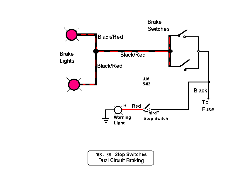
Brake Light Switch Wiring Diagrams are crucial for understanding the electrical system of a vehicle and ensuring proper functioning of the brake lights. These diagrams provide a visual representation of the wiring connections and components involved in the brake light circuit.
Why are Brake Light Switch Wiring Diagrams Essential?
- Help in identifying the wiring connections for the brake light switch
- Aid in troubleshooting electrical issues related to the brake lights
- Show the interaction between different components in the brake light circuit
How to Read and Interpret Brake Light Switch Wiring Diagrams
To effectively read and interpret Brake Light Switch Wiring Diagrams, follow these steps:
- Identify the components and their symbols on the diagram
- Understand the wiring connections and color codes
- Follow the flow of the circuit from the power source to the brake lights
Using Brake Light Switch Wiring Diagrams for Troubleshooting
When facing electrical problems with the brake lights, refer to the wiring diagram for guidance. Here’s how you can utilize the diagram for troubleshooting:
- Check for continuity in the wiring connections
- Inspect the components for any signs of damage or malfunction
- Trace the flow of the circuit to identify the source of the issue
Safety Tips for Working with Brake Light Switch Wiring Diagrams
Working with electrical systems and wiring diagrams requires caution and adherence to safety practices. Here are some safety tips to keep in mind:
- Always disconnect the battery before working on the electrical system
- Use insulated tools to prevent electrical shocks
- Avoid working on the wiring when the vehicle is running
- Double-check the wiring connections before reassembling the components
Brake Light Switch Wiring Diagram
Brake Light Switch Circuit Wiring Diagram

Basic Brake Light Switch Wiring Diagram

The Ultimate Guide: E36 Brake Light Switch Wiring Diagram

[DIAGRAM] Fj Cruiser For Brake Light Switch Wiring Diagram – MYDIAGRAM
![Brake Light Switch Wiring Diagram [DIAGRAM] Fj Cruiser For Brake Light Switch Wiring Diagram - MYDIAGRAM](http://www.thumpertalk.com/uploads/monthly_09_2014/post-198959-0-87748100-1410466744.jpg)
E36 Brake Light Wiring Diagram

Brake Light Circuit Diagram
