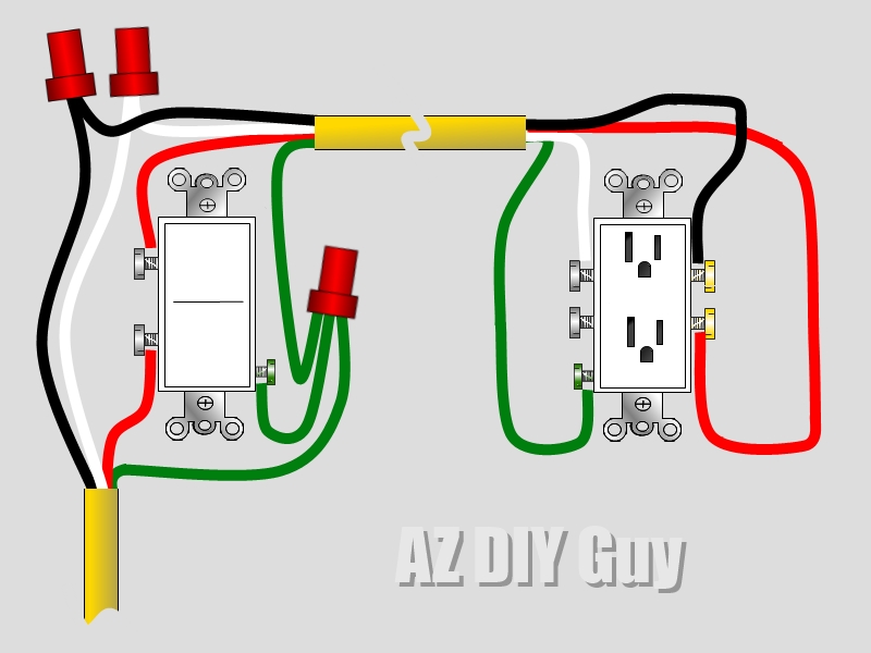
Understanding Electrical Receptacle Wiring Diagram is crucial for any electrician or DIY enthusiast looking to work on electrical systems. These diagrams provide a visual representation of how electrical outlets are wired in a building, helping to ensure proper installation and troubleshooting.
Why Electrical Receptacle Wiring Diagrams are essential
Electrical Receptacle Wiring Diagrams are essential for several reasons:
- They help ensure proper installation of electrical outlets.
- They provide guidance on how outlets are connected to the electrical system.
- They assist in troubleshooting electrical problems.
- They help ensure compliance with electrical codes and safety standards.
How to read and interpret Electrical Receptacle Wiring Diagrams effectively
Reading and interpreting Electrical Receptacle Wiring Diagrams can be daunting for beginners, but with some guidance, it becomes easier:
- Start by familiarizing yourself with the symbols used in the diagrams.
- Follow the wiring lines to understand how outlets are connected to the electrical system.
- Pay attention to color codes and labels for wires and connections.
- Refer to the legend or key provided in the diagram for clarification on symbols and abbreviations.
Using Electrical Receptacle Wiring Diagrams for troubleshooting electrical problems
Electrical Receptacle Wiring Diagrams are invaluable tools when troubleshooting electrical issues:
- Identify the problem area on the diagram and trace the wiring to locate the issue.
- Check for loose connections, damaged wires, or faulty components based on the diagram.
- Use a multimeter to test for continuity and voltage at different points in the circuit.
- Refer to the diagram to ensure proper reconnection of wires after troubleshooting.
Importance of safety when working with electrical systems
When working with electrical systems and using wiring diagrams, safety should always be a top priority:
- Turn off the power at the breaker before starting any work.
- Use insulated tools to prevent electric shocks.
- Avoid working in wet conditions to prevent electrical hazards.
- Double-check connections and follow proper wiring practices to avoid short circuits or fires.
Electrical Receptacle Wiring Diagram
How to Wire an Outlet and Add an Electrical Outlet (DIY) | Family Handyman

Electric Receptacle Wiring Diagram

Home Outlet Wiring Basics – Wiring Flow Line
/wiring-electrical-receptacle-circuits-through-a-receptacle-1152787-01-2a9a43dca2d04d6597dcfb791a548ff9.jpg?strip=all)
A Comprehensive Guide To Gfci Outlet Wiring Diagrams – Wiring Diagram

Understanding Electrical Receptacle Wiring: A Comprehensive Diagram Guide

Understanding Electrical Receptacle Wiring: A Comprehensive Diagram Guide
