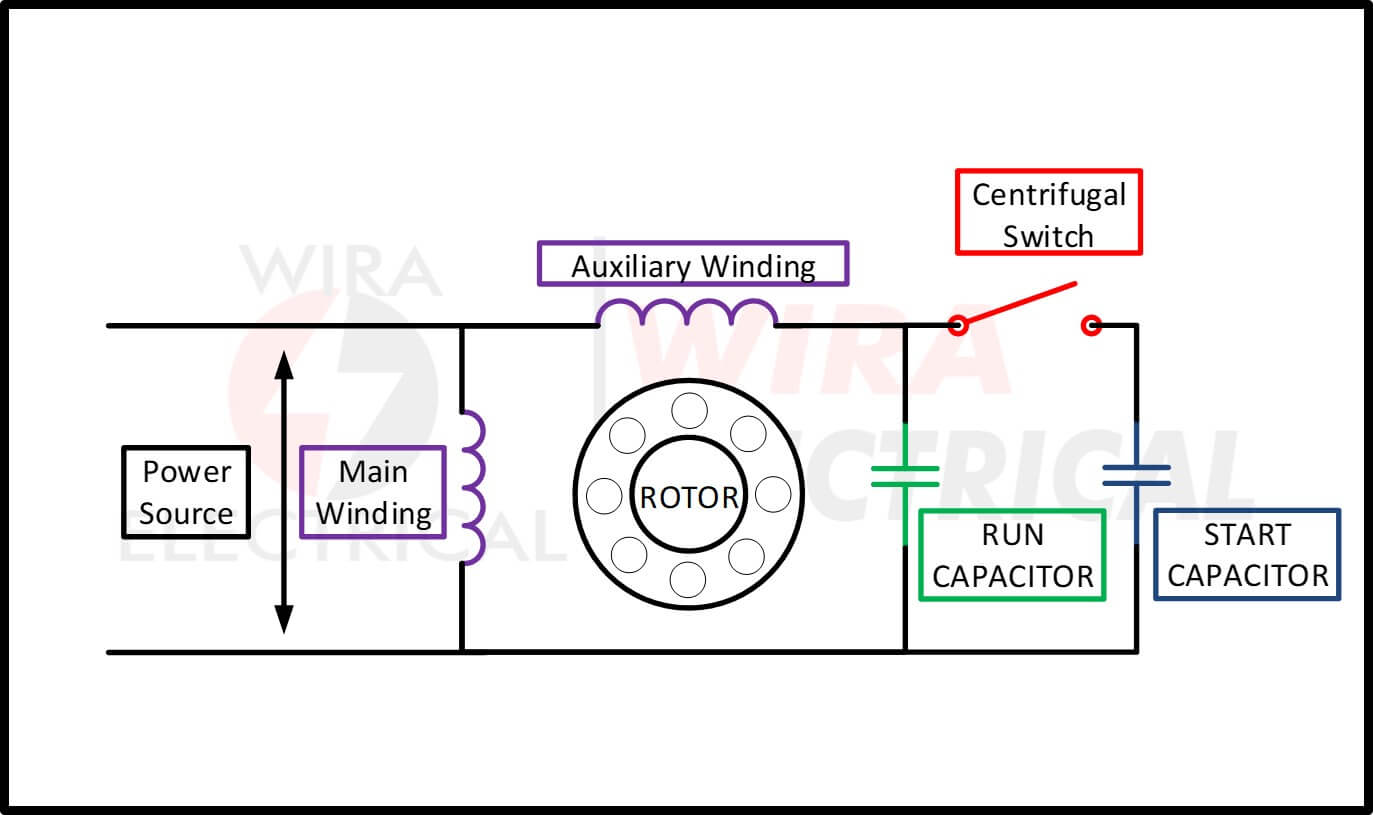
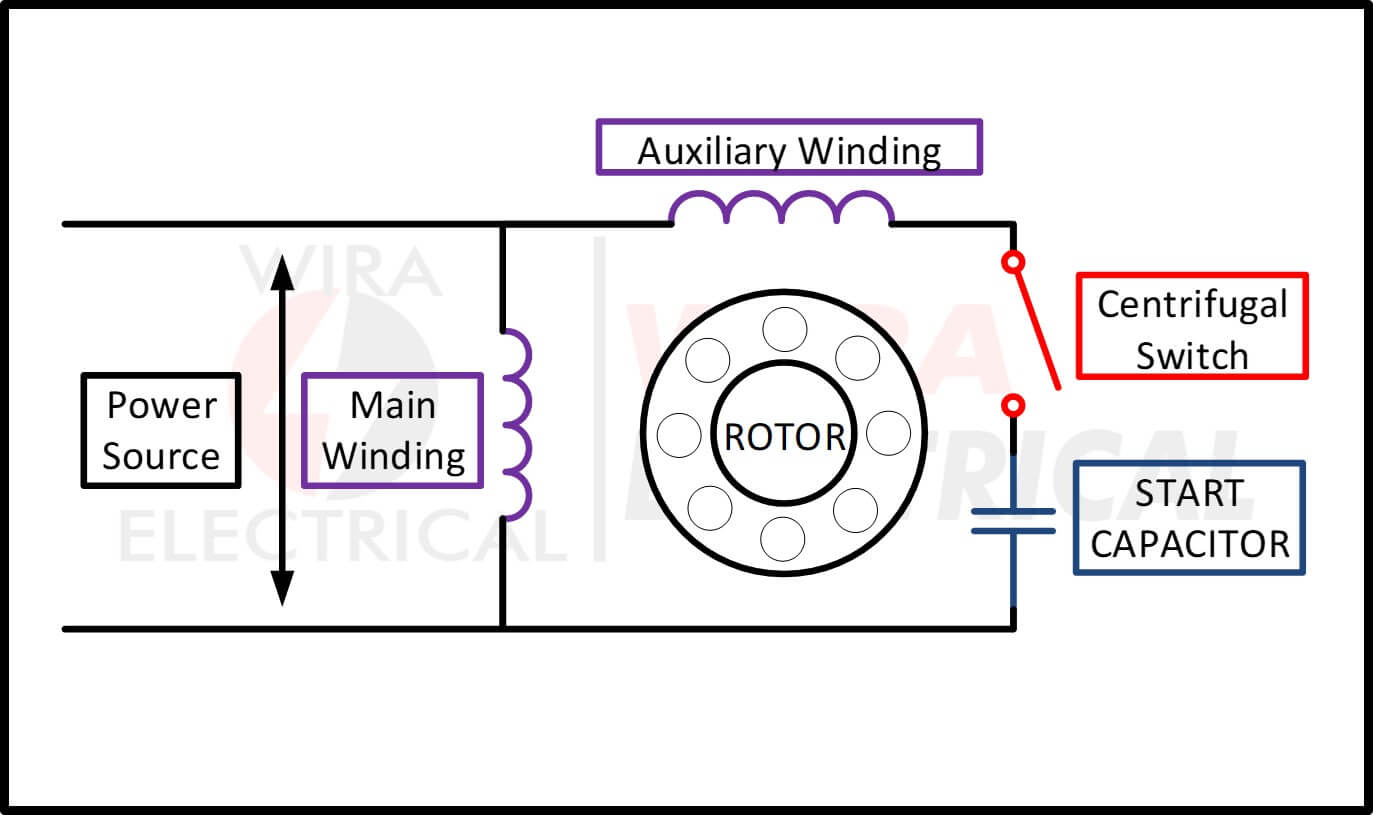
Motor Wiring Diagrams are essential tools for anyone working with electrical systems in various machinery and equipment. These diagrams provide a visual representation of the electrical connections and components within a motor, helping technicians understand how the motor is wired and how it functions. Whether you are installing a new motor, troubleshooting electrical issues, or simply performing maintenance, having access to a motor wiring diagram is crucial.
Importance of Motor Wiring Diagrams
- Ensure proper installation of motors
- Aid in troubleshooting electrical problems
- Help in identifying faulty components
- Ensure safety by following correct wiring configurations
Reading and Interpreting Motor Wiring Diagrams
When looking at a motor wiring diagram, it’s important to understand the symbols and terminology used. Here are some key tips for reading and interpreting motor wiring diagrams:
- Identify the motor type (single-phase or three-phase)
- Locate the main power supply lines and connections
- Understand the layout of the diagram (typically showing the motor, power supply, and control components)
- Follow the wiring paths and connections to ensure correct installation
Using Motor Wiring Diagrams for Troubleshooting
Motor wiring diagrams are invaluable when troubleshooting electrical problems in motors. By referencing the diagram, technicians can:
- Trace the flow of electricity and identify potential issues
- Check for loose or faulty connections
- Test components for continuity and resistance
- Verify proper voltage and current levels
Safety Tips for Working with Motor Wiring Diagrams
When working with electrical systems and motor wiring diagrams, safety should always be a top priority. Here are some important safety tips and best practices to keep in mind:
- Always disconnect power before working on any electrical components
- Use insulated tools and equipment to avoid electric shock
- Wear appropriate personal protective equipment, such as gloves and safety glasses
- Follow proper lockout/tagout procedures to prevent accidental power-ups
- Double-check all connections and wiring before turning on power
Motor Wiring Diagram
Single Phase Motor Wiring Diagram and Examples – Wira Electrical

Single Phase Motor Wiring Diagram and Examples – Wira Electrical

Wiring Diagram For 1 Phase Motor

Three Phase Motor Wiring Diagram Connections

Schematic vs. Wiring Diagrams – Basic Motor Control

Electric Motor Wire Diagram
