Introduction
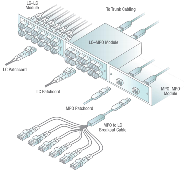
A Patch Panel Wiring Diagram is a visual representation of the connections between different components in an electrical system. It shows how wires are connected to patch panels, which are used to organize and manage cabling in a structured manner.
Importance of Patch Panel Wiring Diagram
Patch Panel Wiring Diagrams are essential for several reasons:
- Help in planning and organizing cabling infrastructure
- Facilitate easy identification and troubleshooting of network connections
- Ensure proper installation and maintenance of electrical systems
Reading and Interpreting Patch Panel Wiring Diagram
Understanding how to read and interpret Patch Panel Wiring Diagrams is crucial for effectively managing electrical systems. Here are some key points to consider:
- Identify the components and their connections
- Follow the flow of wiring from one component to another
- Pay attention to labels and color codes for easy reference
Using Patch Panel Wiring Diagram for Troubleshooting
When faced with electrical problems, Patch Panel Wiring Diagrams can be a valuable tool for troubleshooting. Here’s how they can help:
- Locate and isolate faulty connections or components
- Trace the flow of electricity to identify potential issues
- Guide in making necessary repairs or replacements
Safety Tips for Working with Patch Panel Wiring Diagram
When working with electrical systems and using Patch Panel Wiring Diagrams, it’s important to prioritize safety. Here are some safety tips and best practices:
- Always turn off power before working on electrical systems
- Use proper tools and equipment to prevent accidents
- Avoid working on live wires to prevent electric shocks
- Follow manufacturer’s instructions and guidelines for safe practices
Patch Panel Wiring Diagram
Patch Panel Installation Diagram
Rj45 Patch Panel Wiring Diagram – Organicify

[DIAGRAM] 110 Patch Panel Wiring Diagram – MYDIAGRAM.ONLINE
![Patch Panel Wiring Diagram [DIAGRAM] 110 Patch Panel Wiring Diagram - MYDIAGRAM.ONLINE](https://i1.wp.com/i.stack.imgur.com/JvaKo.jpg)
Patch Panels: A Complete Guide

How To Use a Fiber Optic Patch Panel – Teleweaver

How to Create a Patch Panel Wiring Diagram: Step-by-Step Example
